 Service hotline400-826-2658

Scope of application
SMGQ1-Z dual power automatic transfer switch is our company organized by the scientific and technological elite after two years of painstaking research and development of a new product, launched in late 2014, completely subvert the traditional double power automatic transfer switch shape design style, the design process into the international Industrial design concept, from the product structure, visual appearance, ergonomics, control circuits, etc., to enhance the traditional double-molded plastic automatic dual-switch, so that it has with the international first-class products comparable to the quality and high cost. SMGQ1-Z series dual power automatic transfer switch (referred to as ATS) for rated voltage AC 400V, frequency 50 / 60Hz emergency power supply system. When a power failure occurs, you can automatically switch between the common power supply and standby power, without manual operation to protect the continuity of power supply important equipment. Mainly used for hospitals, shopping malls, banks, chemical industry, metallurgy, high-rise buildings, military facilities and fire power is not allowed to place an important.
Working conditions
○ Ambient air temperature: -5 ℃ ~ +40 ℃, and 24h average does not exceed +35 ℃;
○ Atmospheric conditions: the relative humidity of the atmosphere in the surrounding maximum temperature +40 ℃ not more than 50%, at a lower temperature can have a high humidity, in the wettest month on average minimum temperature +25 ℃, the month Of the average maximum relative humidity of 90%, and taking into account the temperature changes due to condensation on the surface.
○ Altitude: The altitude of the installation site should not exceed 2000m.
○ Pollution Degree: The environmental pollution level of the installation site is Grade 3.
Working mode
SMGQ1-Z intelligent dual power automatic transfer switch has two operating modes: automatic mode and manual mode.
Automatic operation mode: SMGQ1-Z intelligent dual-power automatic transfer switch in automatic mode according to the control function can be divided into self-vote (R), since the vote is not from the complex (S), grid-generator (F) Three, the first two for the grid - power supply system, the latter for the grid - generator power supply system.
Manual working mode: SMGQ1-Z intelligent dual-power automatic transfer switch in manual mode with a common power supply, standby power and circuit breakers and then buckle three work methods.
In the manual mode, the system will not switch automatically.
Commonly used power mode: forced disconnect the backup power supply, access to commonly used power supply; standby power mode: forced to disconnect the common power supply, turn on standby power;
Power and then buckle way: you can disconnect all the two power supply, but also make the circuit breaker and then buckle due to fault deduction.
Basic structural features
SMGQ1-Z series of intelligent dual-power automatic transfer switch is composed of two three-pole or four-pole molded case circuit breaker and its accessories (auxiliary, alarm contacts), mechanical interlocking transmission mechanism, intelligent controller and so on.
Divided into integral, split two structures. The integral type is the controller and the executive body installs on a base; Separate type is the controller installs in the cabinet body panel, the executive body installs in the base by the user installs in the cabinet body, the controller and the implementing agency uses about 2 meters long Of the signal line connection.
Its features are:
○ between the two circuit breakers with reliable mechanical interlock devices and electrical interlock protection, the complete elimination of the possibility of closing two circuit breakers at the same time;
○ intelligent controller using SCM as the control core, hardware is simple, powerful, easy to expand, high reliability;
○ intelligent control circuit layout design, the use of power sampling and single-chip control separation, from the hardware structure to overcome the electromagnetic interference phenomenon;
○ With short circuit, overload protection, overvoltage, undervoltage and phase loss automatic switching function and intelligent alarm function;
○ automatic switching parameters can be set in the external freedom, with the operation of intelligent motor protection;
○ signal cable through the FLUKE instrument channel testing, anti-near-end crosstalk, attenuation crosstalk, return loss, to meet the permanent link test standards;
○ The installation of the switch controller provides users with a strong autonomy, remote installation only accessories (signal cable RJ45) can be connected to the corresponding port.
○ controller part of the same type of products on the basis of the previous electronic components optimized to do more to match the operation of the entire product;
○ Product appearance into the international design concept, more beautiful generous and practical;
○ Innovation in the organization made the following improvements:
Terminal Wiring Diagram
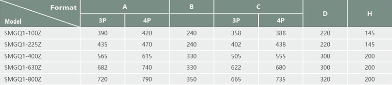
Outline and mounting size (mm)
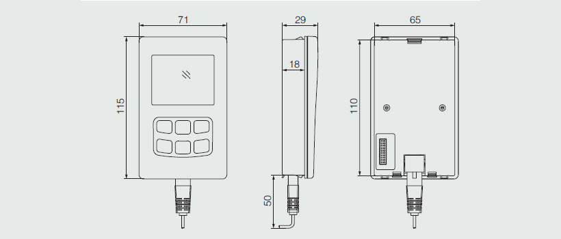
Split controller shape and installation dimensions (mm)
Controller features and functions
This product uses B-type controller; through the control button to set the workpiece workpiece mode and conversion parameters;
Through the display can be directly display and display commonly used measurement and control parameters, these parameters include the voltage delay time;
Fire linkage control function: The intelligent controller control has the group passive fire signal input terminal. Signal input using optocoupler isolation, anti-interference ability; and with a set of passive feedback signal input terminal, the switch can be in place signal to the fire equipment;
Generator start and stop control function: the controller has a set of relay dry node to control the generator start and stop, and can manually set the generator start delay time and stop delay time (need access DC15-30V auxiliary power );
You can remove the display panel installed in the switchgear door, the user does not need to open the door can be used to observe the state of the switch.
Terminal and wiring instructions
○ Automatic operation mode indication;
○ Manual operation mode indication;
○ Fault indication: When the switch is faulty or load short-circuit caused by circuit breaker trip after the indicator light;
○ Common power supply voltage parameter display area: display the common power supply voltage parameter and conversion delay time in the working state, and display the setting item symbol in the setting state;
○ Common power supply side power circuit breaker is closed, disconnect instructions;
O Set status indication;
○ Standby power supply circuit breaker is closed, disconnect instructions;
○ Fire linkage activation indication;
○ Common power supply voltage measurement time and frequency units;
○ A, B, C phase;
○ standby power supply voltage, time, frequency units;
○ Standby power supply voltage parameter display area: display standby power supply voltage parameter and conversion delay time in working state, and display setting project parameter in setting state;
○ generator start signal indication;
○ Automatic / manual switch mode selection button: In normal use as automatic, manual conversion mode selection, in the set state to save and exit the function;
○ Common power switch button: In the manual control mode, if the normal power supply is normal, press this button to force switch to the normal power supply; in the setting state, this button is the setting item on the flip button;
○ Backup power switch button: In the manual control mode, if standby power is normal, press this button to switch to the standby power supply; in the setting state, this button is the setting item,
○ In the manual control mode, press this button to switch to the trip position if any of the two power supply is normal. In the setting state, this button is the setting parameter minus button.
○ Fault search button: When the switch is faulty, the fault light on the display screen will be on, press this button to inquire the detailed fault code of the switch; in the setting state, this button is the setting parameter plus button;
○ Setting button: Press this button to enter the parameter setting menu of the controller.