 Service hotline400-826-2658
Scope of application
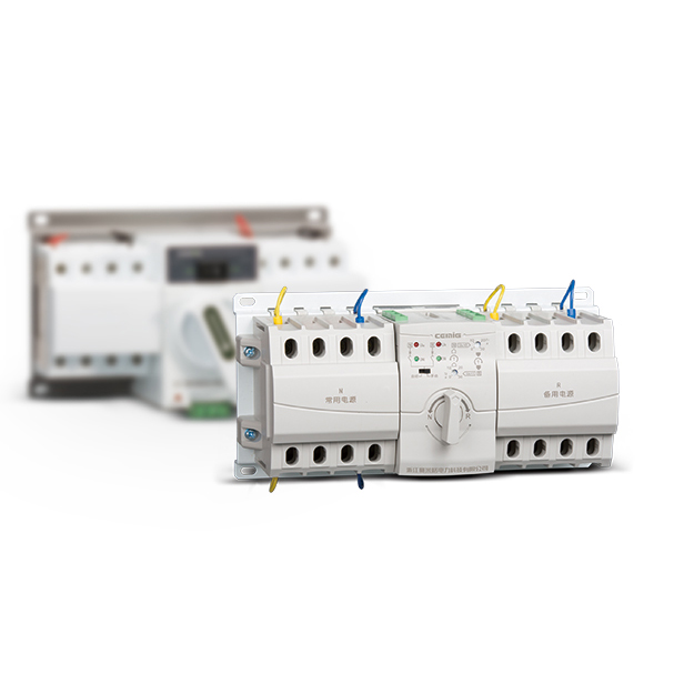
The new design of SMGQ1-63Z series of dual power switch is based on the power switch technology in-depth research and development, from the product structure, control unit, the implementation of the unit, electromagnetic compatibility and other aspects of the new design, fully subvert the traditional dual power automatic transfer switch Of the design concept. The smallest size of the dual power automatic transfer switch, the product structure is compact, easy to install; modular design to improve the continuity of power supply products, energy-saving effect is better than other similar products.
Products meet GB / T14048.11 standards, and through the "CCC" certification and KAMA certification standards.
Working conditions
○ Ambient air temperature: -5 ℃ ~ +40 ℃, and 24h average does not exceed +35 ℃;
○ Atmospheric conditions: the relative humidity of the atmosphere in the surrounding maximum temperature +40 ℃ not more than 50%, at a lower temperature can have a high humidity, in the wettest month on average minimum temperature +25 ℃, the month Of the average maximum relative humidity of 90%, and taking into account the temperature changes due to condensation on the surface.
○ Altitude: The altitude of the installation site should not exceed 2000m.
○ Pollution Degree: The environmental pollution level of the installation site is Grade 3.
Features
Products using modular design, the implementation of components, transmission, control circuit completely independent and convenient replacement.
○ mechanical interlock device using gear transmission, completely eliminate the possibility of closing at the same time;
○ compact product appearance, is currently on the market the smallest of the same type of product;
○ controller control circuit layout using the power supply and sampling power supply and single-chip control separation, from the hardware structure to overcome the electromagnetic interference;
○ Product operating power supply voltage range: AC 150 ~ 265V;
○ Power consumption of products is small, the maximum peak power consumption of 4.8W, only other similar models of power consumption of 20%;
○ Product features, with start generators, fire linkage, closing delay and other functions;
○ modular design, the components of the interchangeable performance, easy installation;
○ can install a variety of implementation of circuit breakers;
Technical performance
Dual power automatic transfer switch according to the power supply voltage state, and the user set the work mode, decide whether to switch from one power supply to another power supply. Its main functions and features are shown in the following table:

Basic structure
SMGQ1-63Z series dual power supply is composed of two small circuit breakers and their accessories, mechanical interlock transmission mechanism, intelligent controller. Products with three-phase sampling detection function, while installed in the dual-power circuit breaker to maintain the original overload and short circuit protection.

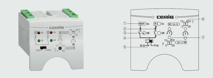
Controller Features
The toggle switch on the controller sets the operating mode of the controller and the rotary potentiometer adjusts the switching delay parameter.
Fire linkage control function: The controller has a set of passive fire signal input terminals. Signal input using optical isolation, anti-interference ability; and with a set of passive feedback signal output terminals can switch the signal in place to return to the fire fighting equipment.
Generator start and stop control function: the controller leaves a set of relay dry node to control the generator start and stop.
On the basis of economic type of voltage monitoring from single-phase to three-phase monitoring.
Controller technical parameters
Operating power supply voltage range: AC 150 ~ 265V
Working temperature: -20 ℃ ~ +60 ℃
Power consumption: ≤ 5W
Conversion delay: 0s ~ 30s adjustable
Return delay: 0s ~ 30s adjustable
Terminal and wiring instructions
○ 101,102 three-pole switch commonly used power supply zero line terminal (either one pole can be);
○ 201,202 three-pole switch backup power supply zero line terminal (either one pole can be);
○ 301 ~ 303 Common Power Supply External Status Indicator Signal Output (AC230V 0.5A);
○ 301 - Signal common zero line 302 - Common power supply signal output 303 - Common power supply closing signal output
○ 401 ~ 403 Standby power supply External status indicator signal output (AC230V 0.5A);
○ 401 - Signal common zero line 402 - Standby power signal output 403 - Standby power supply closing signal output
○ 501 ~ 503 Generator start control signal output terminal.
○ When the standby power supply is a self-starting generator set, the user can complete the automatic start generator function by connecting 501 ~ 503 terminals to the generator controller, 501 ~ 503 is a group of 3A passive relay dry nodes, 503 is the relay common 503 and 501 open, if the common power failure and standby power is dead, 503 and 501 closed, while the 503 and 501 closed, 503 and 501 are closed, And 502 disconnect the generator start signal generator after the success of the switch to automatically switch to standby power supply side of the load in the standby power supply process if the common power back to normal, the controller after the return delay control switch to the common Power, circuit breaker closed 503 and 501 after the closure of 3 seconds delay, 503 and 502 disconnect to send a shutdown signal.
○ 601 ~ 604 fire linkage control port; This interface is used to remote control the switch to cut off the power after the fire equipment alarm.
○ 601,602 - fire linkage control signal input, the interface can only be connected to a group of external normally open passive contact (if the fire equipment to send signals for the active signal, you must first transfer through a small relay and then The relay will normally open contact access controller, otherwise it will burn the controller), when the external contact is closed, the controller immediately switch control switch to the sub-gate position to cut off the load power at the same time through the 603 and 604 terminals return signal to the fire control center;
○ 603,604 - internal for a group of normally open relay dry node for fire action return signal purposes; terminal in normal time for the normally open, when a fire signal into the controller and the switch to the sub-switch
The gate positions 603 and 604 are turned on.
Note: When the fire linkage function starts automatically switch will stop working, to make the switch to normal conversion, you must first remove the fire signal and then control panel on the automatic / manual switch after a switch to restore the normal conversion.