 Service hotline400-826-2658
Scope of application
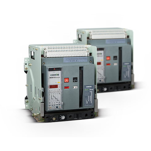
SMGW1 series universal circuit breaker (hereinafter referred to as circuit breaker), for AC 50Hz, rated working voltage 400V, 690V, rated current 6300A and below the distribution network, used to distribute power, protection lines and power equipment, Under the voltage, short circuit grounding fault; the circuit breaker with intelligent protection, selective protection accuracy, can improve the reliability of power supply to avoid unnecessary power outages.
Products can be on the line or down into the line, drawer type circuit breaker with isolation.
Meet the standards: GB 14048.2 and IEC / EN 60947-2.
Model and meaning
Working and mounting conditions
○ ambient air temperature: the upper limit of not more than +40 ℃; lower limit of not less than -5 ℃; 24h the average does not exceed +35 ℃.
Note: (1) the lower limit of -10 ℃ or -25 ℃ working conditions, when ordering the user must be declared to the factory; (2) the upper limit of more than +40 ℃ or lower limit of less than -25 ℃ work Conditions, the user should consult the factory.
○ Elevation: The installation site is not more than 2000 meters above sea level
○ Atmospheric conditions: relative humidity of air not exceeding 50% at a maximum temperature of + 40 ° C A relatively high relative humidity can be tolerated at a lower temperature, for example 90% at 20 ° C, for occasional changes due to temperature changes Condensation should take special measures.
Pollution degree: Grade 3.
○ Installation category: the main circuit and circuit breaker undervoltage release coil, power transformer primary coil installation class IV, the rest of the auxiliary circuit, control circuit installation category III.
○ Use category: B class
○ Installation conditions: The circuit breaker should be installed in accordance with the installation requirements of this manual, the circuit breaker vertical tilt of not more than 5 degrees.
Product Categories
○ By installation method: fixed; drawer type.
○ According to the mode of operation: electric operation; manual operation (maintenance, maintenance)
○ According to the number of points: three poles; four poles.
○ Release type: intelligent over-current controller; under-voltage instantaneous (or delay) action release; shunt release
○ Intelligent over-current controller function: H type (communication type); M type (common type); L type (economy) Three types of controller, its function as shown in Table 1.
Technical parameters and performance
The basic parameters of the circuit breaker are shown in the following table

1. Arcing distance is zero 2. The breaking capacity of the table into the same line from top to bottom
2, the temperature coefficient: As the ambient temperature of the circuit breaker thermal trip characteristics and temperature rise have an impact, so the need for high temperature circuit breaker derating the following table

Note: In a variety of ambient temperature conditions, the measured circuit breaker terminal temperature reached 110 ℃ as a benchmark
Elevation derating factor: The electrical performance of the circuit-breaker can be corrected by referring to Table 3 (b) if the altitude is more than 2000 m above the applicable working environment.
![]()
Intelligent over - current controller protection features and functions
Intelligent controller protection features shown in Figure 1 ~ Figure 2
Intelligent controller protection features shown in Figure 3 to Figure 4
Release current setting Ir and tolerance

Note: When there are three sections of protection, the setting value can not cross, and IR long delay over-current protection inverse time action characteristics

Note: 2.0Ir1 time then I2T = (1.5Ir1) 2tL calculation, where tL is 1.5Ir1 when the action time, set by the user.
Short time delay current protection

The ground fault protection characteristic is short delay time definite time limit, see table 6 definite time action time and returnable time, the ground fault factory setting time is "OFF".
If the user orders no special requirements, the factory will be intelligent release according to the following table configuration.

Note: IR for the long delay protection setting current, Isd for the short delay protection setting current, Ii for the instantaneous protection setting current, Ig for the ground protection setting.
Features
○ Main protection function (The function of the controller has been set according to the requirements at the time of delivery. If you need to reset, please contact with us)
Short-circuit instantaneous protection, ground or residual current definite time and inverse time protection, N phase protection, phase failure caused by the current imbalance protection, the load is anti-counter-current protection, short circuit protection, short-circuit time delay time- Time monitoring and other protection.
Features
○ Measurement and operation monitoring
Real-time measurement of the power grid operating parameters, such as: frequency power factor active power: real-time indication of operating status, such as: fault status, alarm status system self-diagnostic status, normal operation.
○ Query function
Running parameter query, protection parameter setting value query, history fault record query, self-diagnosis fault information query and power grid measurement parameter query and other functions.
○ Parameter setting function
The following protection parameters can be set directly on the front panel of the controller: current value and time value of long-time overload protection, inverse current value of short-circuit short delay protection, definite time current value and time value, instantaneous protection current value, Current value and time value, N phase protection setting value, grounding current or residual current protection current value, time value and inverse time coefficient, unbalance value and time value of current unbalance protection, harmonic influence coefficient.
The following operations can be performed on the front panel of the controller: System clock adjustment (only when this function is selected), and tuning the internal parameters of the system that can be set by all programmer (without programmer, but need password).
○ Programming interface function
It provides the interface with the programmer. It can modify some specific parameters, such as the function setting of signal output contact, the way of voltage measurement, system clock, protection characteristic curve, thermal memory function, communication address and communication baud rate.
○ Communication network function (this function is only available for H type function controller)
Controller provides standard RS485 interface, Modbus or Profibus-DP or DeviceNet protocol can be used to achieve data transmission to meet the different monitoring system "four remote" requirements.
○ Test function
Test function sub-instantaneous tripping simulation test and non-tripping simulation test two kinds:
(1) instantaneous trip simulation test: circuit breaker can be instantaneous action of the tripping test, after the action can display the circuit breaker's inherent action time.
(2) non-tripping simulation test: select the simulation test current system for non-tripping test, alternately after the test shows the test current and the test current in the system delay time and simulation test fault category.
○ Self-diagnosis function
The controller itself appears some fault diagnosis alarm.
○ Fault clock function (optional)
Used to record the time of failure, can record the occurrence of the failure of the year, month, day, hours, minutes and seconds. (Can record up to 8 times)
○ Historical data recording function (optional)
Used to record the four-phase current, three-phase voltage, frequency, power, power factor, active power, recorded every half hour once, can be recorded for three months.
○ Load monitoring protection function
Load monitoring is to control the different load of circuit breaker, in order to guarantee the power supply of main load as far as possible. Load monitoring can be used to pre-alarm, can also be used to control the load branch. The controller is programmable to output two passive signal contacts for load monitoring.
○ MCR on-off and over-limit trip function (optional)
On-off is the fault that the grid is in fault status before the circuit breaker closes. At the moment of closing, a current greater than the set value of MCR is generated. The controller breaks the circuit breaker in an instantaneous way through the analog circuit. This function only in the closing moments 1OOms) play a role. Over-limit trip refers to the circuit breaker in normal operation, when the short-circuit current exceeds a certain value (usually the circuit breaker limit current), the controller through the analog circuit to instantaneous way to break the circuit breaker, this function is not instantaneous set value Impact.
○ Remote, local and set position setting functions (H-type controller only) The controller can set the three status positions of "remote control", "local" and "setting", adopt digital position lock, Operation to achieve, for the network when the permissions set to "remote control", through the host computer to achieve the four remote control operation.
M-type and H-type difference:
M-type intelligent controller and H-type intelligent controller in the function of the difference there are two points:
(1) The function table function of the M-type controller is optional, while the H-type controller does not need to be selected for the basic configuration.
(2) H-type controller has networking and remote local control and set the three-position selection function, while the M-type controller is not.
○ Communication protocol
ModbusRTU is included and can be transferred to ProfibusDP or DeviceNet via an external module.
Operating Performance of Circuit Breakers
Structure Overview
Structure Overview
○ Drawer type circuit breaker
Drawer-type circuit breaker from the circuit breaker body and drawer seat composition. Drawer seat on both sides of the rails, rails on the activities of the guide plate, the circuit breaker body frame on the left and right guide plate. Drawer-type circuit breaker through the circuit breaker body on the bus into the drawer seat bridge contacts to connect the main circuit. Shake the handle of the lower beam of the drawer holder to realize the three working positions of the drawer circuit breaker (there is a position indication beside the swing handle), and there are three position locks to more reliably determine the position and prevent the body from slipping.
"Connection" position: the main circuit and the secondary circuit are connected.
"Test" position: The main circuit is disconnected and separated by an insulating barrier. Only the secondary circuit is switched on, and the necessary operation test can be performed.
"Separation" position: the main circuit and the secondary circuit all disconnected. In the "separation" position To remove the circuit breaker body, you must remove the swing out of the handle.
Drawer type circuit-breakers have mechanical interlocks that allow the circuit-breaker to be closed only in the connected position or in the test position. In the middle of the connection and test can not be closed.
○ Interlocking mechanism
The interlocking mechanism is installed on the right side plate of the circuit breaker, and the cable tie is interlocked (Figure 8). The circuit breaker is interlocked with the interlocking circuit breaker (Figure 9). When one of the circuit breakers is in the closing state , The other can not be closed, interlocking institutions installed by the user.
○ Leveling circuit breaker interlock
Structure Overview
○ Interlocking circuit breaker (The following figure shows the three circuit breakers with interlocking interlocking.) If two circuit-breaker interlocks, only the uppermost circuit breaker should be removed.
Wiring diagram
○ SMGW1-2000 ~ 6300 controller is the basic function of M-type circuit diagram
○ SMGW1-2000 ~ 6300 auxiliary switch from the four normally open four normally closed independent contact composed of secondary circuit wiring diagram
○ Intelligent controller wiring
1 #, 2 #: auxiliary power input, when the auxiliary power supply for the DC, 1 # is the positive side.
3 #, 4 #, 5 #: Fault trip contact output. Contact capacity of AC380V, 3A.
6 #, 7 #, 8 #, 9 #: two circuit breaker state auxiliary contact, the contact capacity is AC380V, 3A. If the user, 6 #, 7 # can output normally closed contact.
25 #, 26 #: external neutral or grounding current transformer input.
SB1: Shunt button (user supplied) X: Closing solenoid Q: Undervoltage release or undervoltage release SB2: Undervoltage pushbutton (user supplied) M: Energy storage motor DF: Auxiliary contact .
SB3: Closing button (user-supplied) F: Shunt release XT: Connection terminal.
Q: Normally open contact SA: Motor microswitch ○: Signal lamp (user-supplied).
Note: (1) If the Q, F, X, M, respectively, when the control power supply voltage is different from the power supply.
(2) Terminal 33 # can be directly power (automatic pre-storage), can also be a series of normally open button after the button to the power (manual pre-storage).